A Network of Networks: Understanding the Internet and the OSI Model
As the Internet has permeated our lives, so too has the lingo associated with it. Terms like “the cloud” have become synonymous with the great unknown. Despite the fact that we spend hours online each day, many people are unaware of how the Internet functions.
Luckily, though complex, the Internet can be broken down into easy to understand pieces. In this blog, I’ll discuss the historical development of the Internet, and how, by understanding the foundation of the network connections that form the Internet, we can also begin to understand the Internet itself.
If you can take one thing away from this blog, let it be this: There is no “cloud” – there is just someone else’s computer.
Terminology
To understand how the Internet works, it’s important to understand the terminology associated with it. The following definitions should help bring you up to speed, at least for the purposes of understanding this blog post:
- Telecommunications Technology refers to any form of distance communications, such as radio, telephone, television, satellite, data communication, or computer networking.
- A node is a computing device that uses some sort of telecommunications technology to connect to other devices. Examples of a node includes your smartphone, laptop, or router.
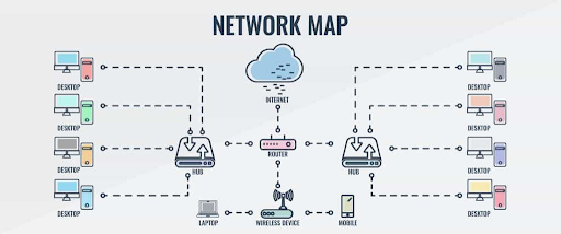
- A network is a group of nodes that are connected by some telecommunications technology and have the ability to communicate with one another. For example, in a network topology of an office space, the network may include desktop computers that are connected to hubs and routers, which in turn connect to the Internet.
- A packet is a variable length data sequence that is sent from one node to another. Similar to a real-life package, the packet has a source, a destination, and all of the data that is being transferred.

History of the Internet
As you can probably guess based on the size and scope of the Internet, the invention of the Internet cannot be credited to a single person. Over the course of several decades, dedicated scientists, programmers, and engineers in multiple countries worked tirelessly to create the “World Wide Web” we have today.
For the purposes of understanding how the Internet works, it’s important to look at several key moments within the creation process.
In the 1970s, computer networks were independently developed and either governmentally-controlled or proprietary. Examples of these include ARPANET(US), the NPL network(UK), CYCLADES(France), or IBM’s System Network Architecture.
The Advanced Research Projects Agency Network (ARPANET) developed by the US Department of Defense can be considered the first workable prototype of the Internet. ARPANET was the first to network to use packet-switching to allow multiple computers to communicate on a single network. Ss well as the first network to implement TCP/IP.
In 1971, the first email send between two separate computers was sent via ARPANET. This fact means that email was actually developed before the Internet itself!
In 1977, when it became obvious that computer programming would continue moving in the direction of a “World Wide Web,” the International Organization for Standardization (ISO) decided to develop a system of standardization for the networks. Using specifications from multiple committees, ISO created the Open Systems Interconnection Reference Model (OSI).
The OSI Model is a specification for how different networks should communicate. The idea behind the creation of the OSI Model was that if everyone followed the model as written, every node would be able to connect to the same network infrastructure. It is thanks to these specifications that you are able to connect to the Internet wherever you travel, regardless of the brand or model of your device and the state or country you are in.
In 1983, ARPANET researchers adopted TCP/IP, which allowed them to connect multiple networks to each other. As most of the use for ARPANET began to come from non-military sources, the US Department of Defense shut down ARPANET in 1990. This lead to the formation of the Internet Engineering Task Force(IETF) which is responsible for guiding the development of the Internet we know and love today.
The Seven Layers of the OSI Model
To understand how the Internet works, it’s important to have a broad understanding of the OSI Model. The OSI Model standardizes the communication functions of telecommunication technology to allow any telecommunication devices to communicate with each other. The OSI Model is broken into seven abstract layers that build on one another to form a complete specification.

The bottom three layers (Layers 1-3) of the OSI Model deal with hardware communication. The top three layers (Layers 5-7) deal with software, and build on the specs and protocols of the lower layers. The middle layer (Layer 4) is the heart of the OSI Model. It is responsible for merging the top and bottom layers into one seamless system. Let’s discuss the layers in more detail:
Layer 1: The Physical Layer
The Physical Layer mostly deals with the transmission of data between nodes over a physical medium. This can include voltage levels, the timing of voltage changes, and the rate of data flow. In other words, the Physical Layer deals with data that travels over a physical connection, such as fiber optic cable or Ethernet.
When you have a networking problem with your home internet, you probably go straight to Physical Layer solutions: check that the router is still plugged in and that all of the cables are connected correctly.
Layer 2: Data Link Layer
The Data Link Layer defines a protocol to establish, manage, and terminate a connection between two physically connected nodes. It is also responsible for detecting and correcting errors that may occur in the Physical Layer.
For example, if you have something interfering with your signal, such as the wireless charger that recently disrupted the signal in my office, the Data Link Layer should be able to perform corrective actions to fix the physical problem.
Layer 3: Network Layer
Now that the first two layers have created a reliable data transmission between two nodes, there needs to be an agreed-upon method for sending and receiving messages between the nodes. That’s where the Network Layer comes in.
The Network Layer specifies how nodes can send packets(variable length data sequences) to other nodes, even if they’re in a different network. Just like a real-life package, every packet that is sent has a source, as destination, and the data being transmitted. As part of this process, the Network Layer also defines how nodes are given addresses (e.g. the MAC address and the IP address). The IP addresses for the nodes are used by the packet to identify the source and destination.
Routers (just like the one currently set up with your home Wi-Fi) are a crucial component in the Network Layer. They are responsible for directing, or “routing,” the information between networks. However, at this level, the routing sequence is very unreliable and information is frequently lost if not combined with the higher layers.
Layer 4: Transport Layer
The Transport Layer makes the data sending in the Network Layer more robust. It is responsible for transferring packets between nodes while maintaining quality of service. The Transport Layer relies on two main protocols:
- Transmission Control Protocol (TCP): TCP is a complex protocol that guarantees successful data transfer. When you send a packet via TCP, you will know if the node on the other end successfully received the packet. Though this mode is reliable, it also requires a lot of overhead. Oftentimes, to get one packet across to the destination node you’ll have to send three or more packets in total.
At the beginning of every connection, TCP conducts what is referred to as the three-way handshake. When you want to transfer data, the initiating node will send a message to the receiving node to let it know that it wants to send a packet. The receiving node will acknowledge the message by sending a sequence number, or shared ID, over which the packet can be sent. The initiating node will then send an acknowledgment of the receiving node’s acknowledgement and will then begin to send the data.
2. User Datagram Protocol (UDP): UDP is a simpler protocol than TCP. With UDP, you do not have the guarantee that your packet will get to the destination node. However, if it does get to the destination node, you have a guarantee that the whole packet will get there (there are no half deliveries).
While it may seem like TCP would always be the way to go (after all, why wouldn’t I want to know that my data made it to its destination?), there are certain situations where the overhead of TCP can be a hindrance. For example, in a high-latency situation such as online gaming, if you waited for every packet to get to its destination on time in a sequential order (as TCP guarantees), you would have noticeable lag time for players. By using UDP, online gaming is able to occur in real time.
The Transport Layer is involved in every node to node transmission; any time you load a website, send an email, or play an online game with a friend, your ability to connect is dependent on the Transport Layer.
Layer 5: Session Layer
The Session Layer establishes and managing connections between nodes of the lifetime of the connection. While it has its own responsibilities, on a broad level most of the Session Layer’s function overlaps with that of the TCP in Layer 4.
It’s important to remember that the OSI Model is a specification about how things should work in theory. As we all know, in practice things don’t always work as clearly as it seems like they should. In my opinion, the Session Layer is a great example of this. When people are creating their own networks and alter the OSI Model by merging layers or skipping protocols, the Session Layer is frequently the layer that is affected because of its overlapping responsibilities.
Layer 6: Presentation Layer
The Presentation Layer is responsible for the formatting and delivery of data (usually text) for display. When data is transmitted between nodes, characters are sent as numbers (known as binary). The Presentation Layer breaks data into its binary representation and sends it through the lower layers as packets via electrical impulses.
Layer 6 is also responsible for serialization, character encoding, and encryption. The Presentation Layer is typically where encryption is implemented. The OSI Model does not have specific protocols for encryption or other security measures, as these can be modified based on the security required for a specific node or network.
Layer 7: Application Layer
The final layer is the Application Layer. The Application Layer is the layer that is used by most software applications. It is therefore the most user-friendly and developer-friendly. This is also the layer that we software developers at Grio use most frequently.
Most protocols established in the Application Layer are implemented on top of TCP or UDP. For example, the HTTP protocol is located in the Application Layer and sent over a TCP connection. HTTP is the request that your browser sends when it wants to render a webpage or when an application is attempting to fetch data from a server.

As you can see in the sample HTTP request above, HTTP is implemented as text sent in a specific format over TCP. The first line of an HTTP request specifies the HTTP action and resource you are making a request for. The second line is the web address that you are sending the request to. The remaining request headers then specify the types of responses you want to receive and how you want to receive them.
You may notice that the web address is a website, not a MAC address or an IP address. If the website you are trying to access is one you’ve never accessed before, the request will first be sent to a Domain Name System (DNS) server. The DNS server will take the web address and send back the corresponding IP address. Most computers store all of these DNS server interactions in their cache so they don’t have to perform this extra step each time.
As you can see, every single action you perform on the Internet is actually made up of many complex interactions occurring in multiple networks almost instantaneously. Using the OSI Model as a roadmap, you can begin to understand how these interactions shape the framework of the Internet. You can also begin to appreciate the grandeur of our current high-speed system.